| The following is a small example taken from the assembly manual that gives you a step by step building guide for your plane. You have a check-list and you may refer to the drawings. For more details we have a CDROM with all the drawings that you may enlarge for a better view of the parts or assembly. |
| |
| 2.1.1.1. - Front spar |
| |
|
Step 1
(method C)
(drawing 2/6) |
Assemble the following parts using 3/32" Clecos in pre-punched holes : | |
| |
| |
T4-S-L001 |
| |
T4-S-R001 |
| |
T4-S-006 |
| |
T4-S-007 | |
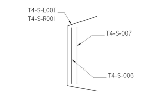 | |
| In the middle of the spars there are eight (8) holes of larger diameter than the others. These large holes are to attach the horizontal stabilizer to the fuselage. This operation will be done later. Do not put rivet in the (12) others holes of the fronts spars, the T4-S-086 & T4-S-087 part will be joined later. |
| |
| |
|
|
| |
|
Step 2
(drawings 3/6 and 4/6) |
On drawings (3/6 and 4/6), look for rivet holes to be used to attach ribs and skin panels and identify them with a marker (Sharpie pen). When assembling the front spar, there is no need to enlarge or put rivets in these holes because other parts (ribs and skin panels) will be joined there later. | |
| |
|
Step 3
(method A)
(drawing 2/6)
|
Enlarge the holes not identified from the previous step; the required hole diameters are specified by the color code on drawing (2/6.) | |
| |
|
Step 4
(method B)
|
Deburr the enlarged holes: all Clecos must be removed in order to deburr both sides of the enlarged holes on each part. When deburring is completed, re-assemble the parts with Clecos (method C). | |
| |
|
Step 5
(method D)
|
Finally, install the appropriate rivets in the holes that are not marked. Rivet diameters are specified in the color code shown on drawing (2/6). | |
| |
|
Step 6
(method F)
|
Perform a visual inspection of the assembly.
| |
| |
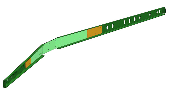
| The following figure illustrates the locations where rivets have been installed; rivets have also been installed at same locations on the second half of the assembly (the R/H side is a mirror image of the L/H side): |
| |
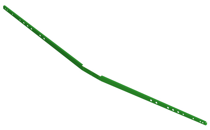
| The completed assembly should look like this : |
| |
|
 |